
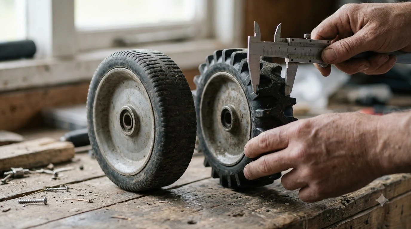

How to troubleshoot a robot mower hall effect wheel sensor? Start by powering down the mower and clearing physical debris around the drive wheel, then perform a hard power cycle before inspecting the motor wiring harness and testing the sensor’s voltage output with a multimeter. Because brushless drive motors rely on hall effect sensors to track rotor position and wheel speed, even a loose connector or clogged axle can trigger a wheel motor fault. Walking through non-invasive checks first lets you isolate a simple blockage or temporary controller glitch from an internal motor failure.
The short answer
- Clear mechanical obstructions first: Grass clippings, twigs, or mud wedged behind a drive wheel prevent rotor rotation and cause the control board to log a wheel motor or sensor error.
- Perform a full power reset: Removing the safety key and disconnecting the battery or charging station for at least 15 minutes clears transient logic faults in the drive controller.
- Inspect the wiring harness and pins: Moisture, vibration, and grass buildup around the wheel housing can loosen or corrode the multi-pin hall sensor connector on the mainboard.
- Verify voltage switching with a multimeter: Supplying low DC voltage to the sensor power wires while rotating the wheel by hand confirms whether the hall switches toggle cleanly between high and low states.
- Know when to replace the assembly: Most robot mower wheel motors are sealed brushless units, meaning an internal sensor failure usually requires replacing the entire drive motor rather than soldering individual components.
What a hall effect wheel sensor does inside a robot mower
A hall effect wheel sensor uses magnetic fields to tell your robot mower’s mainboard exactly how fast and in which direction each drive wheel is spinning. Inside modern brushless DC (BLDC) wheel motors, permanent magnets mounted on the rotating rotor pass over stationary hall effect switches arranged on a small circuit board.
Every time a magnet’s north or south pole sweeps past a sensor, the switch changes its electrical output state. The mower’s microcontroller counts these rapid pulses to synchronize motor phase commutation, calculate wheel odometry, and maintain straight-line tracking across slopes. When the mainboard sends power to a wheel motor but fails to receive expected pulse signals back, it immediately halts operation to prevent the motor windings from overheating or burning out.
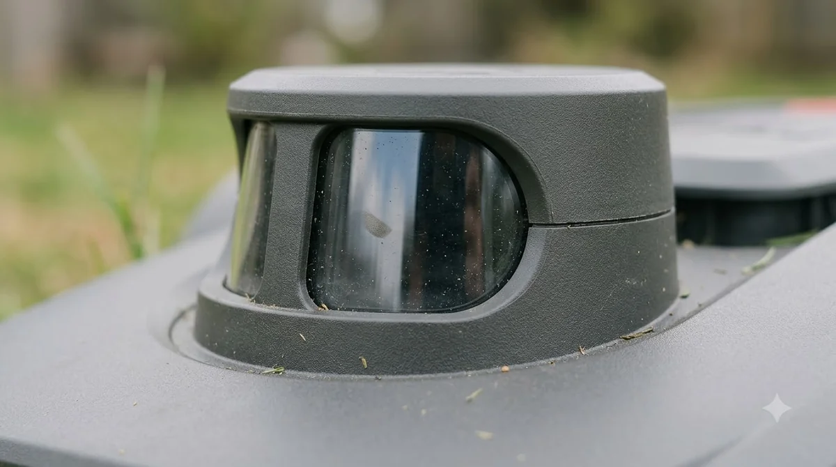
Depending on the manufacturer, a faulty hall sensor reading does not always display as a dedicated sensor code on your app or screen. On many platforms, the control board reports generic wheel drive warnings such as “wheel motor blocked,” “wheel motor overloaded,” or an E2 wheel motor fault, as documented in Husqvarna Automower wheel motor support documentation.
Common symptoms and probable causes
Identifying how your mower behaves right before it stops helps narrow down whether you are dealing with external resistance, a wiring fault, or a failed internal sensor. Rather than tearing down the chassis immediately, match the symptom pattern on your lawn to the most likely root cause.
| Observed behavior | Likely cause | First diagnostic check |
|---|---|---|
| Mower stops in thick grass or on a slope with a wheel motor fault | Mechanical drag or high current draw stalling the rotor | Inspect wheel hub and axle for wrapped grass, mud, or twigs |
| Mower jerks, twitches, or spins in circles before halting | One of the three internal hall sensors is not switching | Check sensor connector seating and test signal wire voltages |
| Error appears immediately at startup on flat ground | Disconnected harness, broken wire, or dead sensor board | Inspect cable routing from wheel housing to mainboard |
| Fault clears temporarily after rebooting, then returns randomly | Controller firmware glitch or intermittent moisture intrusion | Execute a 15-minute full power drain and check chassis seals |
When a single hall switch inside a three-phase hub motor stops reporting, the controller loses track of rotor angle during startup. You will often see the affected wheel shudder back and forth a fraction of an inch before the mower shuts down and throws an error alert.
Heads up
Always remove the safety key, turn off the main power switch, and pull the battery pack (if user-accessible) before flipping your mower upside down or reaching near the blades and drive wheels. Also check your warranty terms before opening a sealed chassis, as breaking factory tamper seals on newer units can void coverage.
Step-by-step troubleshooting from outside to inside
Work through these steps in order from least invasive to most technical so you do not disassemble a healthy motor unnecessarily. According to Worx Landroid wheel motor troubleshooting guidelines, physical obstructions around the wheel mechanism account for a large share of wheel error codes.
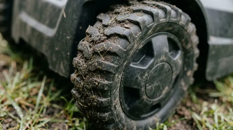
- Clear debris and test free wheel rotation. Power off the mower completely and place it upside down on a clean, flat surface. Inspect the gap between the drive wheel hub and the mower body for tightly wound grass fibers, mulch, pebbles, or dried mud. Remove any debris, then spin both rear drive wheels by hand to confirm they turn smoothly without grinding or binding.
- Run a complete power cycle. If the wheels spin freely, clear any latched controller fault. Turn off the mower, pull the physical safety key, and unplug the charging station (along with any external RTK reference station if your model uses one). Wait at least 15 minutes for internal capacitors to discharge, then reconnect power and restart the unit.
- Swap left and right motor connections to isolate the fault. If your mower uses identical plug-in wheel motor harnesses accessible beneath the top cover, swap the left and right motor plugs on the mainboard as a quick diagnostic test. If the error code moves from the left wheel to the right wheel, the fault lies inside the wheel motor or its cable; if the error stays on the original side, the problem points toward the main control board.
- Inspect the sensor wiring harness and connector pins. A standard brushless wheel motor cable contains thicker phase wires alongside a smaller 5-wire bundle for the hall sensors—typically red for positive voltage, black for ground, and three colored signal wires (often blue, green, and yellow). Look closely for pinched insulation, rodent damage, or green corrosion inside the plug housing, and reseat the connector firmly.
- Test hall sensor output with a digital multimeter. Disconnect the motor harness from the mainboard and supply a steady 5V DC source across the sensor’s red (positive) and black (ground) pins. Set your multimeter to low-range DC voltage, place the black probe on ground, and touch the red probe to each of the three signal wires one at a time while slowly turning the wheel by hand. A healthy sensor toggles cleanly between roughly 0V and near-supply voltage as the internal magnets pass by.
Repair versus replacement: fixing a failed hall sensor
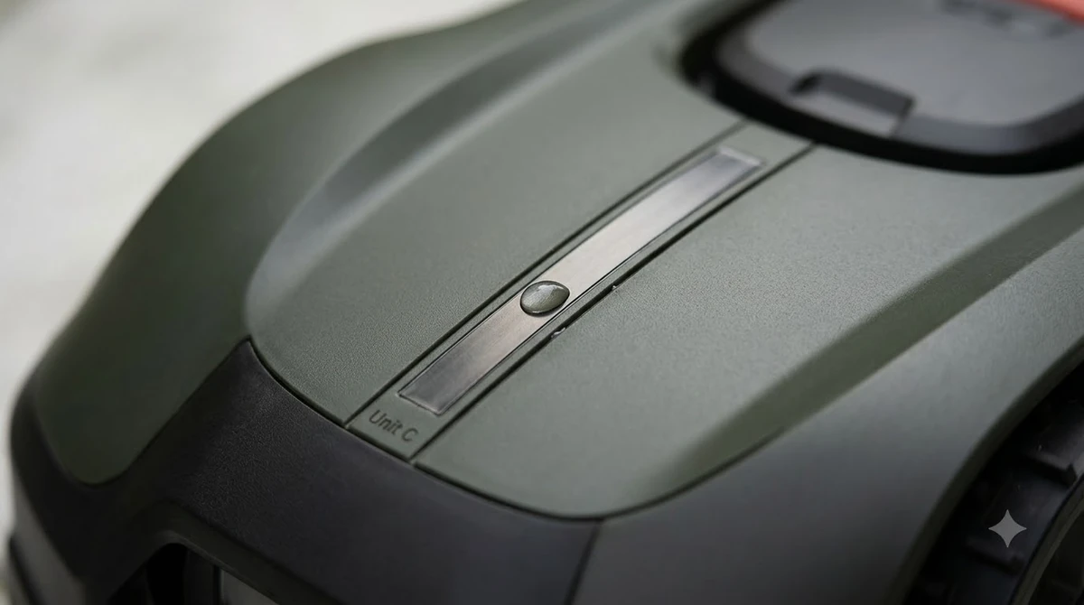
Once multimeter testing confirms that one or more signal lines stay stuck at 0V or supply voltage while the wheel turns, you have to decide between component-level repair and full motor replacement. For the vast majority of residential robot mowers, replacing the complete wheel motor assembly is the practical choice.
Manufacturer drive units are typically pressed, glued, or potted at the factory to survive wet grass, hose spray, and constant vibration. Opening a sealed motor housing requires prying off covers or heating thread-locker, which often damages the weatherproof gasket and invites water intrusion later. Even if you open the housing, surface-mount hall switches on curved stator boards require precise alignment with the rotor magnets so the motor timing stays accurate.
If your mower is still within its warranty window, stop troubleshooting after checking for external debris and contact manufacturer support with photos of the clean wheel hub and a description of when the fault triggers. For out-of-warranty machines, ordering an OEM replacement drive motor restores factory waterproofing and eliminates the guesswork of sourcing matching hall effect ICs.
Preventing future wheel sensor and motor faults
Routine exterior maintenance keeps unnecessary mechanical load off your wheel motors and protects delicate sensor wiring from moisture and heat stress. Keeping your mower clean and operating within its terrain limits significantly extends drive assembly life.
- Clean wheel wells weekly during peak growing season: Wet grass clippings pack tightly behind drive hubs and harden into dense rings that force wheel motors to draw excess current.
- Avoid spraying high-pressure water directly at axle seals: Use a soft brush and damp cloth around the wheel hubs rather than a pressure washer, which can force moisture past rubber shaft seals into the sensor board.
- Keep lawn height within your mower’s cutting range: Running a robot mower through overgrown grass stalls the drive wheels repeatedly, generating heat that accelerates sensor and winding wear.
- Check dock alignment and boundary edges: Ensure the mower does not repeatedly ram hard curbing, exposed tree roots, or steep drop-offs where one wheel spins freely while the other stalls.
Frequently asked questions
Can a robot mower run if one hall effect wheel sensor is faulty?
No. Modern brushless wheel motors depend on continuous rotor position feedback from all three hall sensors to energize the motor coils in sequence. If even one sensor stops sending pulses, the control board immediately halts the drive motor and displays a wheel fault to prevent electrical damage.
Why does my mower show a wheel motor blocked error when nothing is stuck in the wheel?
Most robot mowers do not have a separate error message specifically labeled for the hall sensor. When the mainboard applies power to a wheel motor and sees zero or irregular pulse feedback from the hall sensors, its firmware interprets the lack of detected rotation as a blocked or overloaded wheel.
What voltage should a robot mower hall effect sensor read on a multimeter?
Most brushless motor hall sensor boards operate on a 5V DC supply from the mainboard. When powered with 5V DC and rotated slowly by hand, each of the three signal wires should toggle repeatedly between approximately 0V (low) and close to 5V (high) as the rotor magnets pass the sensor.
How can I tell if the problem is the wheel motor sensor or the main control board?
If your mower model uses identical left and right wheel motor plugs, swapping the left and right motor harnesses at the mainboard is the fastest test. If the error follows the motor to the opposite side, the wheel motor or its sensor cable is faulty; if the error remains on the original side, the mainboard driver circuit is likely at fault.
Sources
- Wheel motor blocked — Automower error message (Husqvarna): Used to verify official manufacturer error terminology and initial wheel obstruction troubleshooting steps.
- Wheel Motor Error | Landroid Vision Error and Status Messages (Worx): Used to confirm E2 wheel motor error causes, safe inspection procedures, and support escalation criteria.
- Hall Effect Sensor Troubleshooting (HMS Networks): Used for fundamental hall effect magnetic target, air-gap, and output signal verification principles.
- Using a Multimeter to Verify the Hall Sensors in Your Electrical Motor (Instructables): Used to verify standard 5-wire brushless motor hall sensor pin color conventions and low-voltage multimeter testing steps.
 Up next7 min readLearnAre Robot Lawn Mowers Safe? What Sensors Do and Don’t CoverUpdated Nov 13, 2026
 8 min readLearnHow to Clean Robot Mower Sensors Safely, Step by StepUpdated Nov 12, 2026
 8 min readLearnWhat Is a Tilt Sensor on a Robot Mower?Updated Nov 11, 2026
 8 min readLearnDo Robot Mowers Have Blade Stop Sensors? What Lift and Tilt Sensors DoUpdated Nov 11, 2026
 10 min readLearnHow to Replace Worn Rubber Treads on Robot Mower WheelsUpdated Nov 19, 2026
 9 min readLearnWhy Does My Robot Mower Spin Its Wheels When Turning?Updated Nov 19, 2026